Controllers / Action Spaces#
Controllers are interfaces between users/policies and robots. Whenever you take a step in an environment and provide an action, that action is sent to a chosen controller that converts actions to control signals to the robot. At the lowest level, all robots in simulation are controlled via joint position or joint velocity controls, effectively specifying where / how fast each joint should go.
For example, the arm_pd_ee_delta_pose controller takes the relative movement of the end-effector as input, and uses inverse kinematics to convert input actions to target positions of robot joints. The robot uses a PD controller to drive motors to achieve target joint positions.
There are a few key elements to remember about controllers in ManiSkill
The controller defines the action space of a task
The robot can have separate controllers for different groups of joints. The action space is a concatenation of the action spaces of all controllers
A single robot may have several sets of controllers that can be used
The next section will detail each of the pre-built controllers and what they do
Passive#
from mani_skill.agents.controllers import PassiveControllerConfig
This controller lets you enforce given joints to be not controlled by actions. An example of this is used for the CartPole environment which defines the CartPole robot as having passive control over the hinge joint of the CartPole (the CartPole task only allows control of the sliding box).
PD Joint Position#
from mani_skill.agents.controllers import PDJointPosControllerConfig
With a PD controller, controls the joint positions of the given joints via actions.
PD EE (End-Effector) Pose#
from mani_skill.agents.controllers import PDEEPoseControllerConfig
This controller has both a pose and a position variant allowing for more intuitive control of just the end-effector (or any link) of a robot. The default options of this controller are set to be the more intuitive option, but there are multiple possible choices.
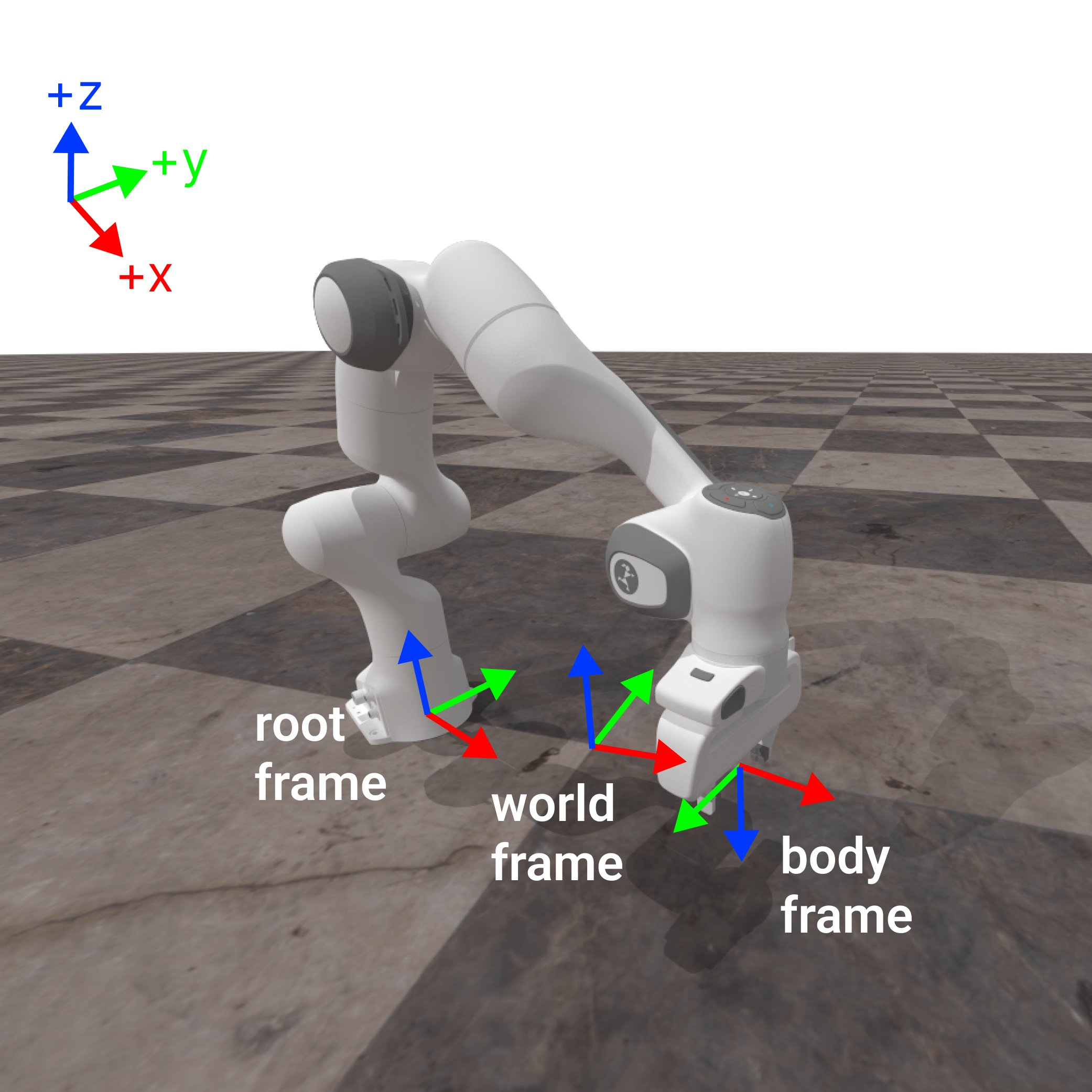
To understand how this works, it is important to first understand that there are 3 relevant transformation frames:
World Frame
Root Link Frame
End Effector / Body Frame (Our PD EE controllers in fact support controlling any link, not just the end-effector)
These are highlighted below and shown with RGB axes where Red = X-axis, Green = Y-axis, and Blue = Z-axis. The desired body to control shown below is a dummy link representing the tool control point (TCP) which is a simple offset from the actual end effector link (hence the origin of the body frame is in the space between the grippers). Note that in ManiSkill/SAPIEN, Z is canonically the natural “up/down direction” which is different to some other simulators.
In this controller the implemented variant is a decoupled control of translation and rotation of the end effector. This means actions taken to translate do not affect the action taken to rotate the end effector around. This results in 6 dimensions of control, 3 for 3D translation, and another 3 for rotation detailed below.
This controller like others offers delta based and absolute control. Internally at each environment timestep given an action, ManiSkill computes the appropriate new target pose of the end-effector and leverages inverse kinematics to compute the joint actions that can best achieve that target pose. Configurations of this controller effectively change how this new target pose is computed.
Delta Control#
This is enabled by default and configured with the use_delta property. It allows the user to submit actions that define deltas in the end-effector pose to move towards. There are 4 frames of control that are permitted, arising from 2 choices for translation multiplied by 2 choices for rotation. The frame is defined by the frame property and follows the naming scheme below
# Naming Scheme is <frame>_translation:<frame>_rotation
# The following 4 frame combos are possible
"body_translation:root_aligned_body_rotation",
"root_translation:root_aligned_body_rotation",
"body_translation:body_aligned_body_rotation",
"root_translation:body_aligned_body_rotation",
# This is the default frame combo
"root_translation:root_aligned_body_rotation"
Translation#
For translation in this controller, the user specifies a delta X, Y, and Z action (in meters if not normalized) indicating how far to move in all those dimensions. Inverse kinematics is then used to determine the required joint actions to achieve the desired translation.
There are two frames for position translation defined in ManiSkill, root frame and body frame translation shown below by setting the corresponding dimension in the action to > 0 and the rest to 0.
Rotation#
For rotation in this controller, the user specifies a delta X, Y, and Z axis rotation (in radians if not normalized) indicating how far to rotate in all those dimensions. They are processed as XYZ Euler angles and converted to a quaternion internally. Inverse kinematics is then used to determine the required joint actions to achieve the desired rotation.
ManiSkill implements two types of rotation based control that are generally the most intuitive to understand and commonly used in real-world robots, which is rotation under one orientation aligned/positioned at another frame. In particular there are two rotation frames supported: root aligned body and body aligned body. A aligned B means rotation in the frame with the same orientation as frame A and same position as frame B. Both frames are shown below by setting the corresponding dimension in the action to > 0 and the rest to 0.
Non Delta Control#
When use_delta=False this is enabled. Actions must then define a 3D position and rotation (via XYZ euler angles) and use the frame root_translation:root_aligned_body_rotation (which is also the default). This kind of control works more similarly to motion planning where you pick a target pose and ManiSkill picks joint actions that try to reach that target pose.
PD EE Pos#
from mani_skill.agents.controllers import PDEEPosControllerConfig
The same as PD EE Pose controller but there is no rotation control and actions are 3 dimensional as a result. There are only two frames defining the frame for translation: "root_translation" and "body_translation"
Deep Dive Example of the Franka Emika Panda Robot Controllers:#
To help detail how controllers work in detail, below we explain with formulae how the controllers are controlling the robot in simulation.
Terminology#
fixed joint: a joint that cannot be controlled. The degree of freedom (DoF) is 0.
qpos( \(q\) ): controllable joint positionsqvel( \(\dot{q}\) ): controllable joint velocitiestarget joint position ( \(\bar{q}\) ): target position of the motor which drives the joint
target joint velocity ( \(\bar{\dot{q}}\) ): target velocity of the motor which drives the joint
PD controller: control loop based on \(F(t) = K_p (\bar{q}(t) - q(t)) + K_d (\bar{\dot{q}}(t) - \dot{q}(t))\). \(K_p\) (stiffness) and \(K_d\) (damping) are hyperparameters. \(F(t)\) is the force of the motor.
Augmented PD controller: Passive forces (like gravity) can be compensated by disabling gravity (they can be computed but this is slow and not necessary).
action ( \(a\) ): the input of the controller, also the output of the policy
Supported Controllers#
The robot is Franka Emika, a.k.a Panda. The DoF of the arm is 7. We use the tool center point (TCP), which is the center between two fingers, as the end-effector.
All “pd” controllers translate input actions to target joint positions \(\bar{q}\) (and velocities) for the internal built-in PD controller. All the controllers have a normalized action space ([-1, 1]), except arm_pd_joint_pos and arm_pd_joint_pos_vel.
For simplicity, we use the name of the arm controller to represent each combination of the arm and gripper controllers, since there is only one gripper controller currently. For example, pd_joint_delta_pos is short for arm_pd_joint_delta_pos + gripper_pd_joint_pos.
Arm controllers#
arm_pd_joint_pos (7-dim): The input is \(\bar{q}\). It can be used for motion planning, but note that the target velocity is always 0.
arm_pd_joint_delta_pos (7-dim): \(\bar{q}(t)=q(t) + a\)
arm_pd_joint_target_delta_pos (7-dim): \(\bar{q}(t)=\bar{q}(t-1) + a\)
arm_pd_ee_delta_pos (3-dim): only control position ( \(p\) ) without rotation ( \(R\) ).
\(\bar{p}(t)=p(t)+a\), \(\bar{R}(t)=R(t)\), \(\bar{q}(t)=IK(\bar{p}(t), \bar{R}(t))\)
arm_pd_ee_delta_pose (6-dim): both position ( \(p\) ) and rotation ( \(R\) ) are controlled. Rotation is represented as axis-angle in the end-effector frame.
\(\bar{p}(t)=p(t)+a_{p}\), \(\bar{R}(t)=R(t) \cdot e^{[a_{R}]_{\times}}\), \(\bar{q}(t)=IK(\bar{p}(t), \bar{R}(t))\)
arm_pd_ee_target_delta_pos (3-dim): \(\bar{p}(t)=\bar{p}(t-1)+a\), \(\bar{R}(t)=R(t)\)
arm_pd_ee_target_delta_pose (6-dim): \(\bar{T}(t)= T_{a} \cdot \bar{T}(t-1)\). \(T\) is the transformation of the end-effector. \(T_a\) is the delta pose induced by the action.
arm_pd_joint_vel (7-dim): only control target joint velocities. Note that the stiffness \(K_p\) is set to 0.
arm_pd_joint_pos_vel (14-dim): the extension of
arm_pd_joint_posto support target velocitiesarm_pd_joint_delta_pos_vel (14-dim): the extension of
arm_pd_joint_delta_posto support target velocities
Gripper controllers (optional)#
gripper_pd_joint_pos (1-dim): Note that we force two gripper fingers to have the same target position. Thus, it is like a “mimic” joint.